Flexible SMT Feeder Solutions At Fanke SMT
In dynamic SMT production environments, feeder availability must match fluctuating project demands — often at short notice. We provide high-quality, on dynamic SMT production environments, feeder availability must match fluctuating project demands — often at short notice. We provide high-quality, original new, tested used feeders — many in as-good-as-new condition — compatible with all major OEM platforms (e.g., Fuji, Yamaha, Juki, Siemens/ASM, Panasonic). Feeders are supplied to your exact specifications (type, pitch, width, interface). Complementing this, we offer dedicated feeder storage units engineered for seamless integration with leading OEM systems — ensuring organization, protection, and quick changeover.
TAKE ME TO YOUR FEEDER
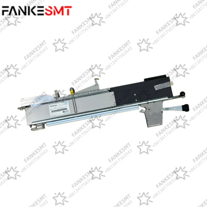
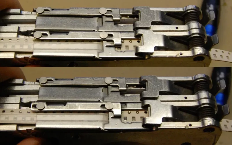
Firstly, it’s worth explaining what part a component feeder plays in a pick-and-place machine, and what it does. Components are supplied on flexible tape, sitting in depressions in its surface and covered by a thin plastic cover film that can be peeled back to reveal the part. Using sprocket holes in the edge of the tape, the feeder advances it from one part to the next while peeling back the cover to expose the part. Feeders are usually positioned in a row along the edge of the machine’s work area, such that its head can manoeuvre itself over the part and pick it up before placing it on the board. In the industrial machines this happens very quickly indeed, so the feeders are substantially built to serve many millions of parts over their lifetime.
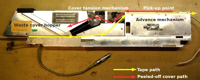
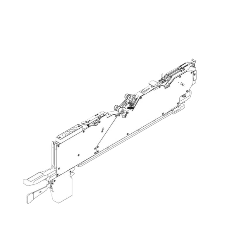
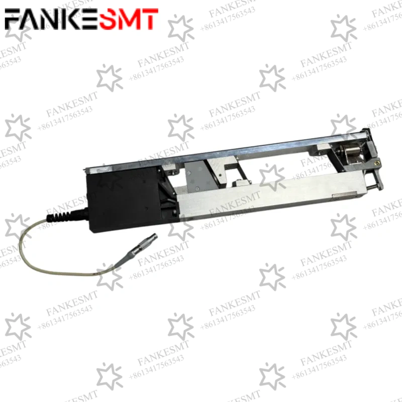
The unit is about 45 mm by 20 mm by 100 mm in size, with a very substantial machined aluminium frame upon which its various components are mounted. It holds not one but two feeders for 8 mm tape, one on either side. Turning it on its side, the front half conceals the feed mechanism with the pick-up point at the top, while at the centre is a tensioning system for the peeled-off cover tape. At the rear is a hopper for spent cover tape, accessible via a spring hatch on the back. On the top at the rear are a pair of membrane buttons, to advance or retard the tape.
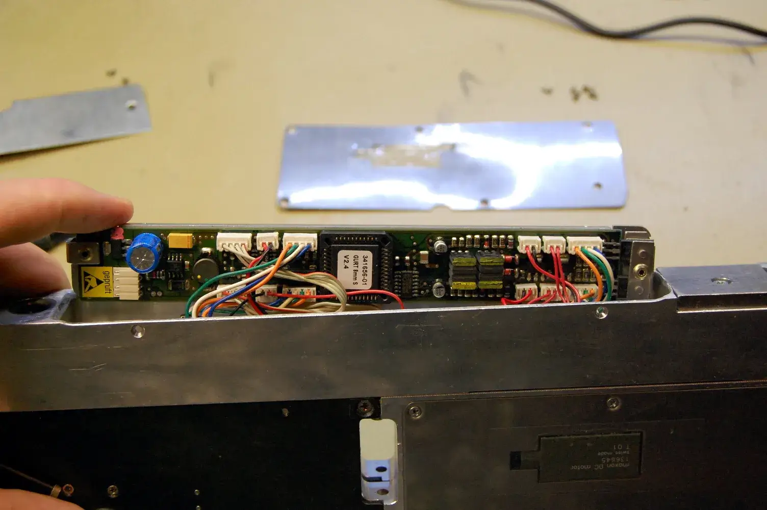
The main mechanisms are easily revealed by releasing the screws holding on their outer panels. In the front is the feed mechanism, which takes the form of a sprocket designed to engage with the holes in the tape. This is driven by a worm drive gear from a motor, which also has an optical encoder to sense how far the tape has been advanced or retarded. Above the motor is a solenoid that operates the shutter, a sliding sheet metal assembly on the top of the unit which exposes the pick-up point.
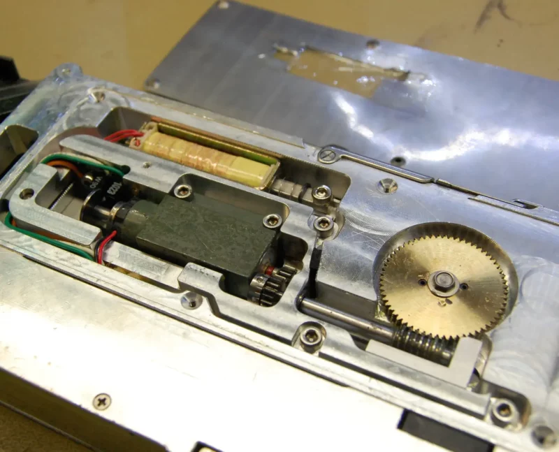
In the centre of the unit is the cover tape tension mechanism. Another motor and sprocket pulls the cover tape past a spring-tensioned roller, that has an optical sensor to feed back its position. The spent cover tape spools into the hopper at the back, from which it can be emptied upon reel changes. The whole machine is controlled by a microcontroller on a narrow PCB in the base of the unit. The guess is that it’s an older Atmel part, but for now it remains covered by a sticker. Communication with the pick-and-place machine is via a serial connection through that Neutrik connector.